Model 506 is the heavy drive shaft version of Model 505. This unit features a 13″ deep frame, 3″ high cleats, 6″ high side rails, and large drive pulley. It is designed to move larger and heavier products up incline and withstand heavy usage.
Standard Specifications
Widths: 12″ – 48″
Lengths: 5’– 25′ (6″ Increments)
Standard Length is 5′, Two Piece Bolt Together
Standard Speed: 60 FPM
Standard Motor: 3/4 HP 230/460/3/60 TEFC
Standard Drive: Top Mount, Right Side
Standard Belt: Black PVC 120 with 3″ high cleats on 12″ centers, Clipper Lacing
Drive Pulley: 8″ Dia Crown Face Rubber Lagged x 1-11/16″
Infeed Pulley: 8″ Dia Crown Face Take Up x 1-7/16″
Frame: 13″ Deep x 10 Gauge
Bearings: Grease Sealed
Others: Base unit includes 6″ high side rails and bottom pan
This unit features a 13″ deep frame, 3″ high cleats, 6″ high side rails, and large drive pulley. It is designed to move larger and heavier products up inclines. This sturdy, solid conveyor is built to last and withstand heavy usage.
Standard Specifications
Widths: 12″ – 48″
Lengths: 5’– 25′ (6″ Increments) Standard Length is 5′, Two Piece Bolt Together
Standard Speed: 60 FPM
Standard Motor: 3/4 HP 230/460/3/60 TEFC
Standard Drive: Top Mount, Right Side
Standard Belt: Black PVC 120 with 3″ high cleats on 12″ centers, Clipper Lacing
Drive Pulley: 8″ Dia Crown Face Rubber Lagged x 1-7/16″
Infeed Pulley: 8″ Dia Crown Face Take Up x 1-7/16″
Frame: 13″ Deep x 10 Gauge
Bearings: Grease Sealed
Others: Base unit includes 6″ high side rails and bottom pan
This lightweight shallow frame conveyor can be used in both horizontal and inclined applications. These units typically convey lighter weight and smaller products like empty plastic bottles or cans, scrap lumber, nuts & bolts, and small stampings.
Standard Specifications
Widths: 4″ – 30″
Lengths: Up to 20′ (6″ Increments)
Standard Length is 4′, Two Piece Bolt Together
Standard Speed: 60 FPM
Standard Motor: 1/3 HP 230/460/3/60 TEFC
Standard Drive: Top Mount, Right Side
Standard Belt: Black PVC 120 with 1-1/2″ High Cleats on 12′ Centers, Clipper Lacing
Drive Pulley: 4″ Dia Crown Face Rubber Lagged x 1-3/16″
Infeed Pulley: 4″ Dia Crown Face Take Up x 1-3/16″
Frame: 6-5/8″ Deep x 12 Gauge
Others: Base unit includes 3-1/2″ High Side Rails and a Bottom Pan
Note: Infeed hoppers and discharge chutes are optional
Adaptable Tooling For Packaging & Palletizing
Tool does not exceed package profile size
Automated changeover
Plug and play to your robot
Longer lifespan than average tooling
Adaptable Tooling Communication
Illustration: Norgren's Adaptaable Packaging and Palletizing Tool Communication
Contol Module Highlights
Communication Protocol: Ethernet IP – communicates what job, when to change, tool health
Power: 24VDC <10 amp type Health Status > Arm position monitoring, Arm status, Vacuum status
HMI (Human Machine Interface:
Starter package for integrators to easily integrate control modules into PC, PLC, or optional additional display
Wireless or wired connection
Operating Software: Java
Autonomous LEvel
Pre-programmed: Store up to 10,000 pre-programmed positions
Programmable: User "Teach-Mode" to add new package sizes
Self-Learning: Automatic input from vision system or barcode reader
Smart Features
Part presence feedback
Condition Monitoring
Key Benefits
User friendly
Plug & Play
Total footprint does not exceed package size
NOrgren Package & Palletizing Tool HIghlights
Tool Weight: 6.8 kg (15 lbs)
Maximum Pay Load: 15 kg (33 lbs)
Vacuum Sourcing: Venturi (size & capacity per application)
Air Supply Required: 15 SCFM at 80 PSI
Vacuum Pads: 4-each 50 mm Bellow Cups (variable per application)
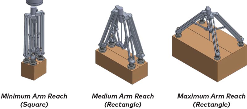
Minimum Arm Reach (Square Package): 120 mm x 120 mm
Maximum Arm Reach (Rectangular Package): 215 mm x 625 mm
Maximum Arm Reach (Rectangular Package): 50 mm x 500 mm
Arm Positioning Sensing: Feedback from Motor Control
Cell/Automation Communication to the Tool, Power: Ethernet IP, 24V <10 amp Typ
HMI: Core software available / HMI optional
Position Change Time (time taken to adapt to new package): < 2 seconds
Maximum Number of Changes per Hour: 600
Technical Dimensions
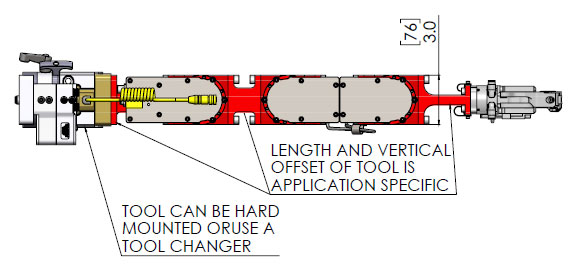
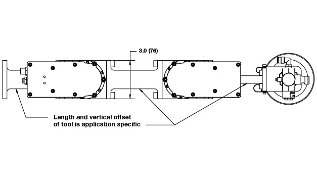
NOrgren's adaptable Package & Palletizing tool minimum to maximum are reach
Applications
Package Handling
Palletizing
Bin Picking
Assembly
Loading and Unloading
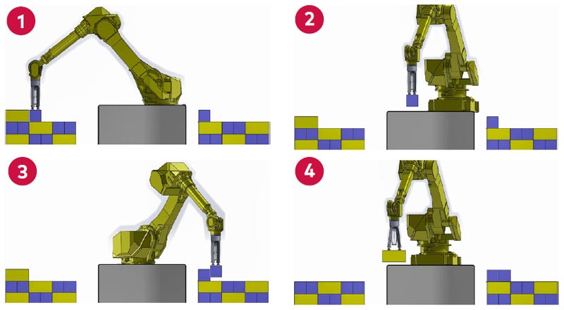
Adaptive Transforming Tooling:Press Load
Conventional Tooling vs. Norgren’s Transforming Tooling
Eliminates the need for manual tool changes and adjustments
Removes the need for lock-out tag-out procedures and potential safety concerns
Faster die changeover times, while removing issues associated with ergonomics and manual labor
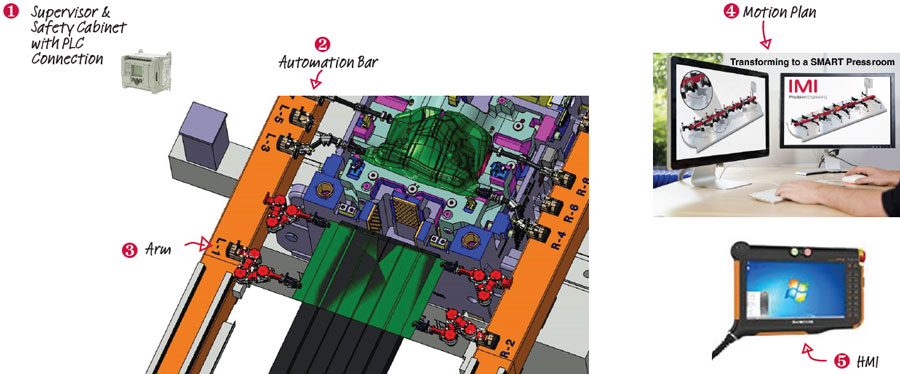
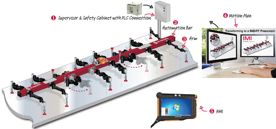
Adaptive Transforming Tooling Communication
Illustration: Norgren's Adaptive Transforming Tooling Communication Illustration
Communication & HMI Highlights
Cell/Automation PLC Communication to TT Supervisor: Ethernet IP – communicates what job, when to change, health of the TT
Supervisor: Stores the jobs with specific motion plans
Number of Jobs: 1000’s of motion plans – positions
Power: 24V <10 amp Type
Arm Communication: Supervisor to Arm joints via can bus
Health Status: Arm position monitoring, Arm status, Vacuum status
Job Change Time: <1 minute
Motion Plan: Offline process which defines individual arm movement timing and position based on system needs. Stored in the Supervisor.
HMI: User friendly intuitive control for Jobs, adjustment, trouble shooting. Wireless, PC, PLC (learn more about the HMI below)
Operating Software: Java
Repair: Replaced components are recognized by the Supervisor and configure automatically – no need to home or calibrate replaced hard-ware
Hardware: Industrial Tablet (Wireless), Pendent, PLC, PC
Status Screen: Provides status. Cell PLC provides the commands for what job, when to change
Adjustment: Provides the ability to adjust position of arms and ability to save
Health: Provides information on the health of the system. Supports Industry 4.0 – tracking, trends, predictive maintenance
Press Loader Product Highlights
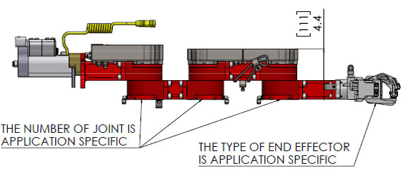
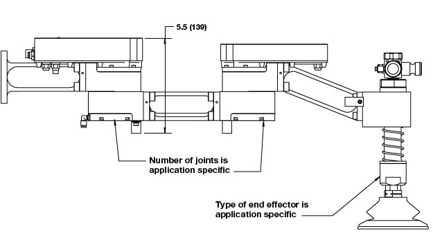
Arm Weight (1 arm, 3 joints): Application Specific, 6.8 kg (15 lbs) as shown
System Weight:Application Specific, 27 kg (60 lbs) as shown
Number of Arms:Application Specific, 4-8 typical as shown
Joints: Application Specific, 3-5 joints per arm typical as shown
Dynamic Arm Rating (locked): 200 Nm (150 ft lb)
Dynamic Arm Rating (unlocked): 30 Nm (20 ft lb)
Maximum Arm Reach: Variable to application needs (limited by dynamic rating)
Safety: Clutch slips at 30 Nm (20 ft lb) when un-locked
Position Sensing: Application Specific, absolute positioning technology joint to joint as shown
Life Span: 15 years, 50,000 Changes
Cell/Automation: Communication to TT, power Ethernet IP, 24V <10 amp Typ
Note: All dimensions (in/mm) are for reference only. All highlight metrics can be customized and are based on the standard 4-arm application.
Applications
Stamping (automotive, white goods)
Adaptive Transforming Tooling: Destacker
The front of a business's press line requires lots of attention and maintenance: from ensuring that multiple blanks are not accidentally put into the press at one time to job changeovers, the process can be tedious and unsafe.
Norgren's Transforming Tooling for the Press Room Destacker eliminates the need for manual job changeovers by automatically adjusting it's position for each job, and includes double blank sensing to protect your press from damages or crashes - so you can focus on what's important.
Conventional Tooling vs. Norgren’s Transforming Tooling
Eliminate hundreds of thousands of dollars in recurring tooling costs
Free up hundreds of square meters of floor space
Eliminate manual tool change and optimize safety
Adaptive Transforming Tooling Communication
Illustration: Norgren's Adaptive Transforming Tooling Communication Illustration
Communication Highlights
Cell/Automation PLC Communication to TT Supervisor: Ethernet IP – communicates what job, when to change, health of the TT
Supervisor: Stores the jobs with specific motion plans
Number of Jobs: 1000’s of motion plans – positions
Power: 24V <10 amp Type
Arm Communication: Supervisor to Arm joints via can bus
Health Status: Arm position monitoring, Arm status, Vacuum status
Job Change Time: <1 minute
Motion Plan: Offline process which defines individual arm movement timing and position based on system needs. Stored in the Supervisor.
HMI: User friendly intuitive control for Jobs, adjustment, trouble shooting. Wireless, PC, PLC (learn more about the HMI below)
Operating Software: Java
Repair: Replaced components are recognized by the Supervisor and configure automatically – no need to home or calibrate replaced hard-ware
HMI HIghlights
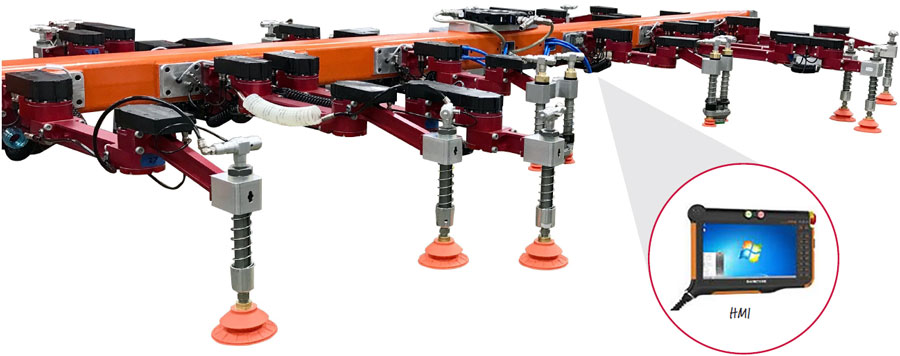
Norgren destacker with integrated HMI
HMI Highlights
Hardware: Industrial Tablet (Wireless), Pendent, PLC, PC
Operating Software: Java
Status Screen: Provides status. Cell PLC provides the commands for what job, when to change
Adjustment: Provides the ability to adjust position of arms and ability to save
Health: Provides information on the health of the system. Supports Industry 4.0 – tracking, trends, predictive maintenance
Destacker Product Highlights
Arm Weight: (1 arm, 2 joints) Application Specific, 6.8 kg (15 lbs) as shown
System Weight: Application Specific, 60 kg (130 lbs) as shown
Number of Arms: Application Specific, 3-16 typical as shown
Joints: Application Specific, 1-3 joints per arm typical as shown
Dynamic Arm rating (locked): 200 Nm (150 ft lb)
Dynamic Arm rating (unlocked): 30 Nm (20 ft lb)
Maximum Arm Reach: Variable to application needs (limited by dynamic rating)
Safety: Clutch slips at 30 Nm (20 ft lb) when un-locked
Position Sensing: Application Specific, absolute positioning technology joint to joint as shown
Life Span: 15 years, 50,000 Changes
Cell/Automation Communication to TT, Power: Ethernet IP, 24V <10 amp Typ
Note: All dimensions (in/mm) are for reference only. All highlight metrics can be customized and are based on the standard 4-arm application.
Applications
Stamping (automotive, white goods)
Glass Manufacturing
Ceramic Manufacturing
Assembly
Packaging
Destacking
Palletizing and Stacking
Watch: Norgren Destacker ready for installation in a press room
The New London Engineering model 420 Floor to Floor heavy-duty inclined conveyor is built for moving large and awkward items from floor to floor. It features a sturdy, heavy-duty frame and a double nose-over discharge that provides a smooth incline to horizontal transition.
Standard Specifications
Widths: Up to 48″
Lengths: 5’– 100′ (6″ Increments) Standard Length is 5′, Two Piece Bolt Together
Standard Speed: 60 FPM
Standard Motor: 1/2 HP 230/460/3/60 TEFC
Standard Drive: Bottom Mount, Right Side
Standard Belt: Black Rubber Rough Top, Clipper Lacing
Drive Pulley: 8″ Dia Crown Face Rubber Lagged x 1-7/16″
Infeed Pulley: 4″ Dia Crown Face Take Up x 1-3/16″
Frame: 5-1/2″ Deep x 12 Gauge
Bearings: Grease Sealed
Standard Supports: 30″ Elevation Top of Belt
Standard Nose-Over: Adjustable Double Nose-Over
Power Feeder: Power Feeders are Optional
The New London Engineering Model 410 Floor to floor conveyor is a medium-duty inclined conveyor built for moving narrow and light items up shorter levels. It features a space-saving shallow frame and a double nose-over discharge that provides smooth incline to horizontal transition.
Standard Specifications
Widths: Up to 30″
Lengths: 5’– 40′ (6″ Increments)
Standard Speed: 60 FPM
Standard Motor: 1/3 HP 230/460/3/60 TEFC
Standard Drive: Bottom Mount, Right Side
Standard Belt: Black Rubber Rough Top, Clipper Lacing
Drive Pulley: 4″ Dia Crown Face Rubber Lagged x 1-3/16″
Infeed Pulley: 4″ Dia Crown Face Take Up x 1-3/16″
Frame: 2-3/4″ Deep x 12 Gauge
Bearings: Grease Sealed
Standard Supports: 30″ Elevation Top of Belt
Standard Nose-Over: Adjustable Double Nose-Over
Power Feeder: Power feeders are optional.
The New London Engineering Model 321's heavy duty frame and pulleys are grooved/notched to provide a track for the rubber guide that is vulcanized to the underside of the belt. This keeps the belt centered for side loading, long run, and short but wide heavy-duty applications.
Standard Specifications
Widths: Up to 68″ Wide
Lengths: 5’– 100′ (6″ Increments)
Standard Length is 5′, Two Piece Bolt Together
Standard Speed: 60 FPM
Standard Motor: 1/2 HP 230/460/3/60 TEFC
Standard Drive: Bottom Mount, Right Side
Standard Belt: Black PVC 120 with “A” Section, “V-Guide”
Drive Pulley: 8″ Dia Flat Face Rubber Lagged x 1-11/16″ with “A” section, “V-Guide”
Infeed Pulley: 4″ Dia Flat Face Take Up x 1-7/16″ with “A” section, “V-Guide”
Frame: 6-5/8″ Deep x 12 Gauge
Bearings: Grease Sealed
Standard Supports: 30″ Elevation Top of Belt
This unit features a frame and pulleys with notches to provide a track for the rubber guide that is vulcanized to the underside of the belt. This keeps the belt centered for side loading, long run, and short but wide medium-duty applications.
Standard Specifications
Widths: Up to 48″
Lengths: 5’– 100′ (6″ Increments)
Standard Length is 5′, Two Piece Bolt Together
Standard Speed: 60 FPM
Standard Motor: 1/2 HP 230/460/3/60 TEFC
Standard Drive: Bottom Mount, Right Side
Standard Belt: Black PVC 120 with “A” Section, “V-Guide”
Drive Pulley: 8″ Dia Flat Face Rubber Lagged x 1-7/16″ with “A” section, “V-Guide”
Infeed Pulley: 4″ Dia Flat Face Take Up x 1-3/16″ with “A” section, “V-Guide”
Frame: 6-5/8″ Deep x 12 Gauge
Bearings: Grease Sealed
Standard Supports: 30″ Elevation Top of Belt
This standard-duty unit features a frame and pulleys with notches to provide a track for the rubber guide that is vulcanized to the underside of the belt. This keeps the belt centered for side loading, long run, and short but wide applications.
Standard Specifications
Widths: Up to 30″ Wide
Lengths: 5’– 100′ (6″ Increments) Standard Length is 5′, Two Piece Bolt Together
Standard Speed: 60 FPM
Standard Motor: 1/2 HP 230/460/3/60 TEFC
Standard Drive: Bottom Mount, Right Side
Standard Belt: Black PVC 120 with “A” Section, “V-Guide”
Drive Pulley: 4″ Dia Flat Face Rubber Lagged x 1-3/16″ with “A” Section, “V-Guide”
Infeed Pulley: 4″ Dia Flat Face Take Up x 1-3/16″ with “A” Section, “V-Guide”
Frame: 6-5/8″ Deep x 12 Gauge
Bearings: Grease Sealed
Supports: 30″ Elevation Top of Belt
New London Engineering's Model 221 is the heavy drive shaft Model 220. This heavy-duty, deep frame slider bed is built for low maintenance and extended use. It is designed for longer, wider, and heavier weight slider bed applications.
Standard Specifications
Widths: Up to 48″
Lengths: 5’– 100′ (6″ Increments) Standard Length is 5′, Two Piece Bolt Together
Standard Speed: 60 FPM
Standard Motor: 1/2 HP 230/460/3/60 TEFC
Standard Drive: Bottom Mount, Right Side
Standard Belt: Black PVC 120, Clipper Lacing
Drive Pulley: 8″ Dia Crown Face Rubber Lagged x 1-11/16″
Infeed Pulley: 4″ Dia Crown Face Take Up x 1-7/16″