Search...

The Shadow® 10 is a light curtain built with the pressroom in mind. With seamless hardware, these rugged light curtains can resist the everyday pressroom grease and grime and simplify programming and day-to-day maintenance. This transition to the Shadow 10 light curtain allows Wintriss to take better control of the Shadow line; we can offer the support, fast repairs, flexibility, and safety features that our customers need.
Magnetic filters use rare-earth or high-strength permanent magnets to capture ferrous and paramagnetic particles from fluids (coolants, oils, hydraulic fluids), protecting downstream systems, reducing wear, and extending fluid life. (MPI’s Eco-Mag is a good example of this technology) cdn.thomasnet.com
Unlike traditional filters, magnetic filters often require no consumables—just periodic cleaning of the magnetic core.
Below are sample specs for MPI / MPI magnetic / return filter systems (note: may vary by model):
Spec | Typical Value / Range |
Maximum Working Pressure | ~ 10 bar (1 MPa) |
Recommended Flow Range | Up to ~3,000 L/min (depending on model and Δp) |
Bypass Valve Setting | ~1.75 bar ±10% (for many models) |
Filter Housing Material | Nylon / GF reinforced (for small models) or aluminum (larger) |
Operating Temperature Range | –25 °C to +110 °C (typical) |
Seal Materials | Standard NBR; optional FPM / Viton for more aggressive fluids |
Mounting Orientation | Vertical (many units are designed vertical mounting) |
Δp Across Element | Filter elements rated to carry up to ~10 bar differential (varies) |
For detailed information on available solutions, please click click on the link above to visit our main Magnetic Lifters page. If you have questions or would like assistance selecting the right equipment for your application, please use our RFQ form (also linked above) or call us at 1‑800‑863‑3164.
MPI’s Magnetic Sheet Separators and Fanner Magnets are engineered to improve productivity, safety, and material flow wherever stacked steel sheets must be separated quickly and consistently. These systems eliminate double‑sheeting and ensure smooth, predictable feeding in stamping, forming, shearing, and automated handling operations.
Magnetic sheet separators—also known as sheet fanners—use induced magnetic fields to create repelling forces between stacked steel sheets. As the magnetic field energizes the stack, each sheet develops a like‑pole charge, causing the sheets to fan apart. This allows operators, robots, or automated equipment to pick one sheet at a time with no sticking, slipping, or doubling.
MPI manufactures two primary sheet‑separation product families: Standard Magnetic Sheet Separators and Pneumatic Automated Fanner Magnets
MPI’s SS Series Sheet Separators are built for reliability in both manual and automated metal‑forming operations. These permanent‑magnet units provide consistent sheet fanning for thin‑gauge ferrous materials, including oily, sticky, or pre‑finished stock commonly used in stamping and fabrication.
The SS Series induces like magnetic poles into the sheet stack. As each sheet becomes magnetized, the repelling forces push the sheets apart, creating a controlled “fan” effect that ensures reliable single‑sheet separation.
MPI’s Pneumatic Automated Fanner Magnets are also sheet separators—engineered specifically for high‑volume, fully automated environments. These units combine powerful rare‑earth magnetics with pneumatic on/off control, allowing precise sheet handling without residual magnetism when the system is disengaged.
Specification | SS Series – Standard Sheet Separators | Pneumatic Automated Fanner Magnets |
Magnet Type | Permanent ceramic (optional rare‑earth upgrade) | High‑strength rare‑earth magnets |
Magnet Control | Always‑on permanent magnet | Pneumatic on/off control |
Housing Material | 100% stainless steel, all‑welded | Lightweight, compact stainless steel/aluminum construction |
Demagnetization Resistance | Less than 0.5% loss over 100 years under normal use | Not applicable (pneumatic shutoff eliminates residual field) |
Power Requirements | None | Compressed air supply |
Typical Applications | Manual or automated sheet de‑stacking, stamping, forming, shearing | High‑volume automated lines, robotic end‑of‑arm tooling |
Sheet Material Compatibility | Ferrous sheets, including oily, sticky, or pre‑finished stock | Ferrous sheets, especially oily or polished materials |
Mounting Options | Standard brackets, custom brackets, wear strips | Designed for integration into robotic tooling or automated systems |
Operating Environment | Harsh industrial environments | Automated production environments |
Maintenance | Maintenance‑free | Minimal; pneumatic system inspection |
Feature | SS Series Sheet Separators | Pneumatic Automated Fanner Magnets |
Primary Function | Permanent magnetic sheet separation | Automated magnetic sheet separation with on/off control |
Best For | Manual or semi‑automated operations | Fully automated, high‑volume production |
Magnetic Strength | Strong (ceramic or rare‑earth) | Very strong (rare‑earth) |
On/Off Capability | No — always active | Yes — pneumatic control |
Residual Magnetism | Always present | Eliminated when turned off |
Integration Level | Floor‑mounted or machine‑mounted | Ideal for robotic end‑of‑arm tooling |
Safety Advantages | Reduces manual handling | Eliminates residual magnetism; safer for operators |
Cost Level | Lower initial cost | Higher initial cost; optimized for automation |
Maintenance Needs | None | Low (pneumatic system checks) |
Ideal Sheet Types | Thin‑gauge, oily, sticky, or pre‑finished ferrous sheets | Oily, polished, or difficult‑to‑separate ferrous sheets |
W-Technologies standard hydraulic shock dampers can eliminate the break through shock associated with blanking operations, therefore minimizing the noise and vibration. Our shock dampers are designed to provide a counter pressure force, upward, at the moment of part breakthrough. Properly sized and adjusted, our shock dampers will eliminate the reverse load or tonnage during blanking. They will also allow you to increase your blanking capacity (tonnage) on each press that has dampers.
Our Application Engineers can help you determine what shock dampers are right for your application. Tell us your press tonnage, material type, material thickness, yield strength, press stroke, available bolster space and we’ll provide you a recommendation.
W-Technologies, Inc. fabricates standard hydraulic shock dampers designed to eliminate the destructive effects of reverse loading.
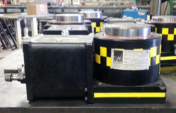
Custom hydraulic shock dampers are beneficial in any blanking, punching or die trimming application of metal, plastics or composites that is experiencing excessive reverse shock, premature die wear, fatigued press components or hydraulic system failure at part breakthrough.
The reverse load released at the moment of material fracture in press blanking, punching and die trim applications generates shock loads that degrade press, tooling life and part quality. Hydraulic shock dampers absorb this energy without derating press capacity. Dampers are installed next to the tooling on the bed of the press and engage a striker plate or counter pressure post at the time in the press stroke when the punch contacts the work material. As blanking force builds, the shock damper pistons retract with little resistance bypassing oil through internal orifices and pressure valves assembled within the cylinder. At the moment of break through, these passages restrict the bypass oil to resist the downward acceleration of the press slide and tooling.
Gap‑frame and C‑frame presses offer easy die access and compact footprints for short runs, prototyping, and specialty forming. Straight‑side and four‑column presses handle large dies and heavy loads for specialty operations.
PRI carries Mechanical Presses from Minster; AIDA; Eagle Press Equipment; Komatsu.
For detailed information on available solutions, please click click on the link above to visit our main Gap‑Frame, C‑Frame, and Specialty Presses page. If you have questions or would like assistance selecting the right equipment for your application, please use our RFQ form (also linked above) or call us at 1‑800‑863‑3164.
Transfer and progressive systems perform sequential operations across multiple die stations in a single line. They are engineered for complex multi‑stage parts and high‑volume production with automated part transfer.
PRI carries Mechanical Presses from Eagle Press Equipment (transfer systems); Bruderer; Schuler.
For detailed information on available solutions, please click click on the link above to visit our main Transfer Presses & Progressive Stamping Systems page. If you have questions or would like assistance selecting the right equipment for your application, please use our RFQ form (also linked above) or call us at 1‑800‑863‑3164.
The Eagle SE Series is a line of heavy-duty eccentric (geared mechanical) presses suited for medium to very high tonnage applications. These presses are built to deliver strong, repeatable performance in demanding operations—especially punching, blanking, and stamping where high force, precision, and ruggedness are essential.
When evaluating or specifying an SE Series press, be sure to provide us with:
If you’re considering an SE Series press for your production line, let's talk. We can help you:
Reach out to PRI today to explore how the Eagle SE Series mechanical presses can elevate your pressroom’s performance.
Pax die doors enclose the point of operation on mechanical power presses to contain fluids and flying objects. They are also act as interlocked barrier guards when fully closed.
If you’re concerned with the overall safety aspect of your press room and are having problems with containing and controlling die lubricant around your press then consider Pax Die Doors as a part of the solution. Like Pax lubrication systems and low profile conveyors, Pax Die Doors were developed by the Pax stamping division.
Windows provide excellent visibility to the point of operation and are easily replaceable.
Interlock switches interface with the press control system to prevent continuous or single stroke operation when the door is open.
Die lubricant troughs catch excess lubricant and provide a capture location at the base of the die door.
Easy open spring loaded low tension T-handle for manual doors engages latch and safety pins.
Machined channel and delrin rollers provide guidance and smooth operation.
The standard Pax Die Door is non-acoustical and manually operated and requires very little effort to open and close. Pax Die Doors provide an interlocked point-of-operation safety barrier and are designed to assist with containing and controlling die lubricants.
The Pax Die Door can be designed with an air cylinder to assist in the operation of the door. By adding a single air cylinder, the Pax door may be controlled via a switch. By utilizing the counterbalance weights in conjunction with the air cylinder, minimal air pressure is required for operating the door. This option may be required for larger press applications and applications that are too high for the operator to completely open and close the door manually.
Pax offers an Acoustical Die Door option for those companies concerned with noise associated with stamping presses.
For detailed information on available solutions, please click click on the link above to visit our main Safety Blocks page. If you have questions or would like assistance selecting the right equipment for your application, please use our RFQ form (also linked above) or call us at 1‑800‑863‑3164.
“The employer shall provide and enforce the use of safety blocks for use whenever dies are being adjusted or repaired in the press.”
Please refer to 1910.217(d)(9)(iv) as referenced in OSHA document:
Regulations: Machinery and Machine Guarding / Standard Number: 1910.217.
Information is also available online from the
American National Standards Institute B11.1-2009 document
Refer to section 9.2.6 “die adjustment, cleaning, or repair.”
Safety blocks are designed to prevent accidental die closure during press setup and maintenance. Safety blocks are constructed from lightweight extruded aluminum or magnesium and are available in fixed lengths with wedges for minor adjustment or adjustable versions. Consideration should be given to the weight of safety blocks as they can sometimes be cumbersome to lift where press bolster heights are well off the floor.
Static load and open height requirements determine the optimal size and style of safety block. See the download sheet for more details or contact our Application Engineers for more information.
Safety blocks provide safety during setup and maintenance for power presses by mechanically and electrically preventing inadvertent die closure.
PRI's 42o Safety Blocks are for smaller presses, with a maximum static load of 35 tons (having a wide span of adjustable heights) and are made of high-strength, lightweight extruded aluminum. Selection of the proper style and size is determined by the press static load and the required open height. Safety blocks using wedges are also available, as well as the standard model 42 for larger presses.
Production Resources Inc.'s die safety blocks are placed between the die punch and holder or ram and bolster with the machine stroke up.
They are rated to support a static load. The static load represents the combined weight of the press ram, ram components (ram-adjust assembly and connection rod[s] or pitman arm[s]), and the upper die.
In some applications, as many as four safety blocks may be required. This is determined by the size of the press bed and the weight the blocks must support. On larger presses, the total slide weight must then be distributed among the quantity of safety blocks required.
The ram is usually adjustable; therefore, wedges or the adjustable screw device is offered to provide a proper fit. If the die takes up most of the space on the die set, it may be difficult to find a place to insert the block. To avoid accidentally stroking the press or leaving the safety block in the die after use, an electrical power cut-off interlock system should be used.
Note: Electrical interlocking of die safety blocks to the machine’s motor and control circuits is required by ANSI B11.19.
The DiPro Sensor Interface (DSI 2) allows you to connect most electromechanical and discrete-output electronic sensors to your die protection control.
Some die mounted junction boxes are not compatible with the DSI 2. See our Application Note
The DSI 2 is available with 8 sensor inputs, and features a built-in 24VDC power supply to power your sensors.
The DSI 2 has built-in pulse stretching on inputs 1-4 (also on inputs 9-12 on 16-input units) to stretch very fast signals (usually from part ejection sensors) out to a duration of 10mSec.
The DSI 2 is a flexible sensor connection solution. It is available with or without front- panel connectors for wiring individual sensors, along with a variety of larger connectors
(including a heavy duty 19-pin M23 connector) for use with die-mounted junction boxes that allow you to connect up to eight sensors to the DSI with a single cable.
Wintriss offers a complete line of sensors and connectivity products including proximity and photoelectric sensors, die-mountable junction boxes, cables, and connectors.
The DSI 2 is compatible with all versions of SmartPAC 2, SmartPAC 1, and DiPro 1500.


Serving North America
HEADQUARTERS
256 Seaboard Lane, Ste. B-104
Franklin, Tennessee 37067
© 2004-2026